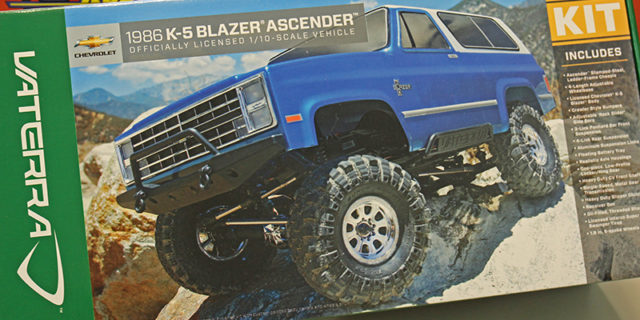
Welcome to Part 1 of our Vaterra K5 Blazer Ascender kit build. The plan is to assemble the kit in relatively stock form at first. As we move forward we will be adding numerous option parts and upgrades to this Blazer build to enhance the overall performance. This is a scale truck at the end of the day, but we want to build it up to be an extremely capable trail rig that can go play with the best of them anytime, anywhere. Now that you know where we are headed with this K5 kit, let’s tear into this build and get started!
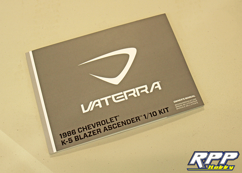
The first thing we always do with a new kit build is sit down and read through the instruction manual a few times to get familiar with the build process and order of assembly.
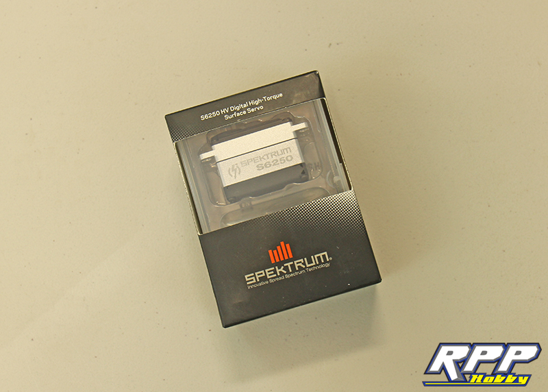
A few of the key components going into our K5 build. First up, the Spektrum S6250 servo will be in charge of our steering. This low profile servo features an all aluminum case and the ability to run up 8.4V for 382 oz-in of knuckle breaking power!
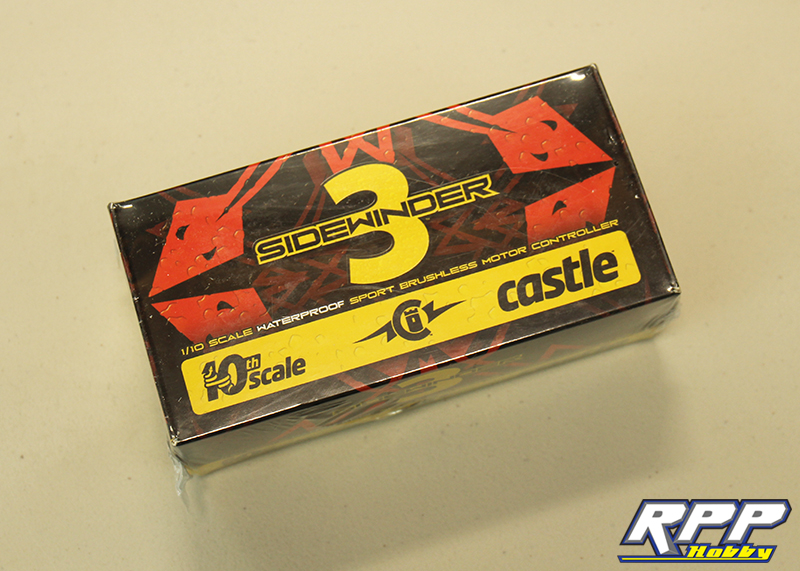
Throttle control will be left up to a trusty Castle Creations Sidewinder SV3 ESC which is waterproof should we ever find ourselves wheeling in the wet stuff.
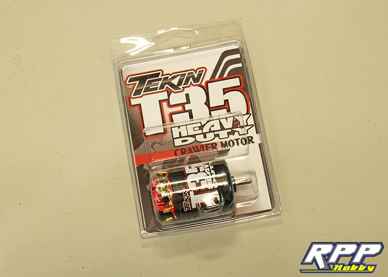
Torque delivery tasks will be entrusted to a Tekin Heavy Duty 35T motor. Smooth on the low end and enough wheel speed to power up climbs.
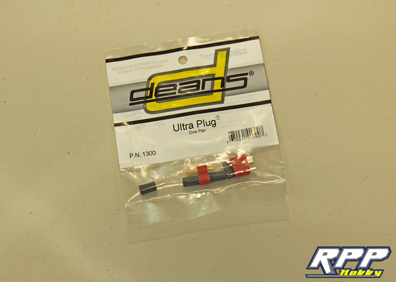
In order to keep a constant current flowing from our battery to the ESC we will be soldering up a pair of Deans Ultra Plugs.
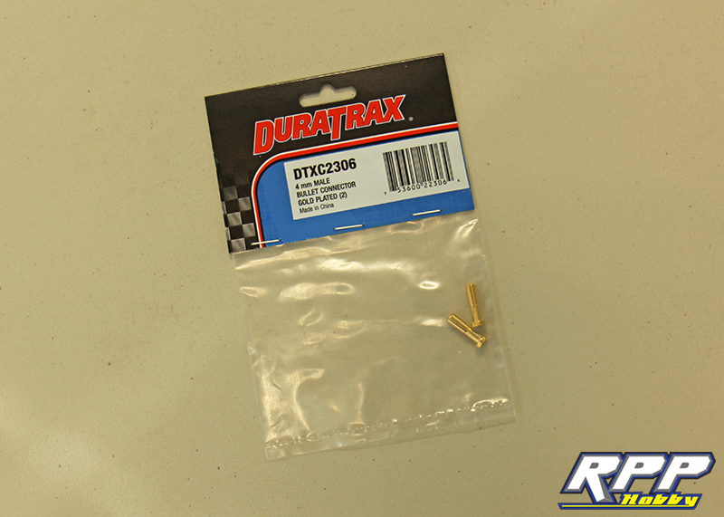
Duratrax 4mm male bullet connectors will provide power to the motor.
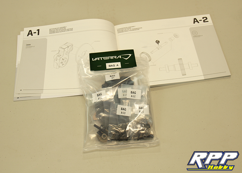
Time to start assembling! Locate Bag A in your Blazer box.
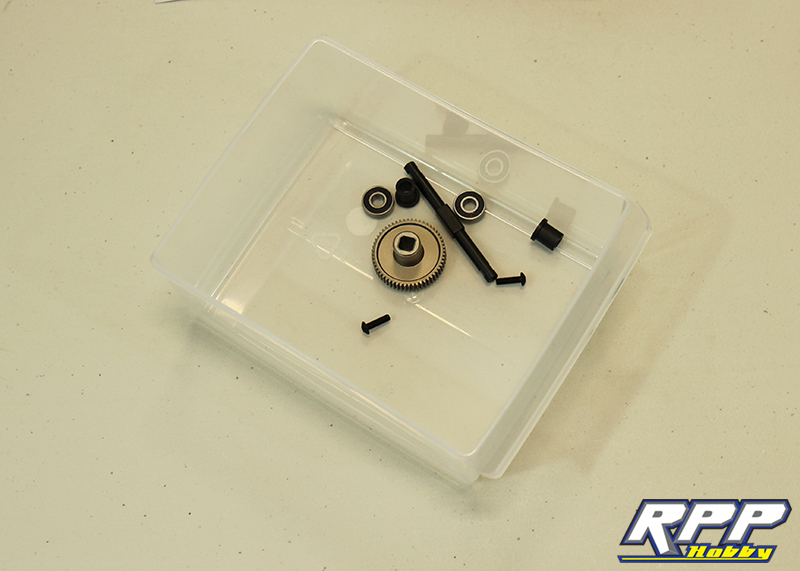
It is always a good idea to keep a small container around to empty your part’s bags into during each step. Don’t want to loose anything during the build process!
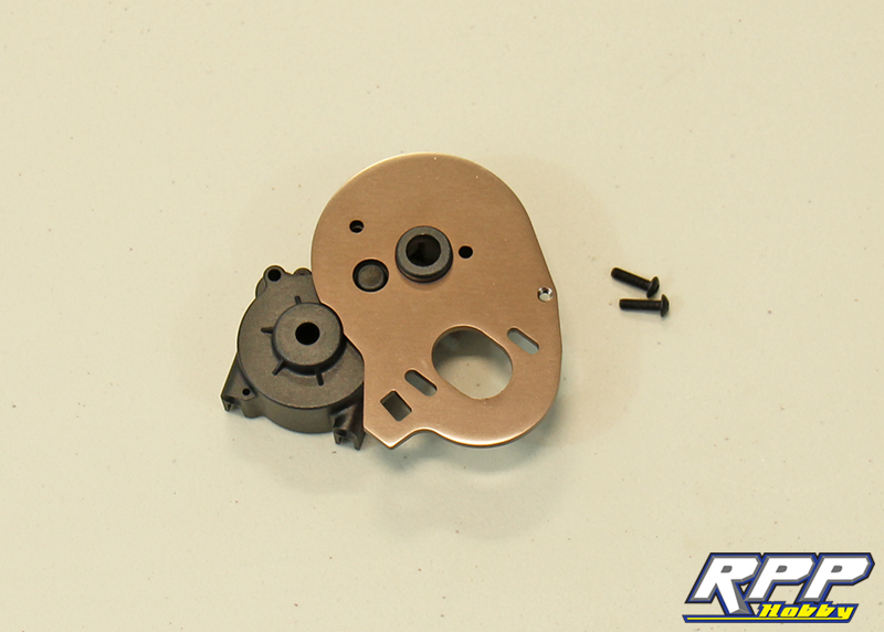
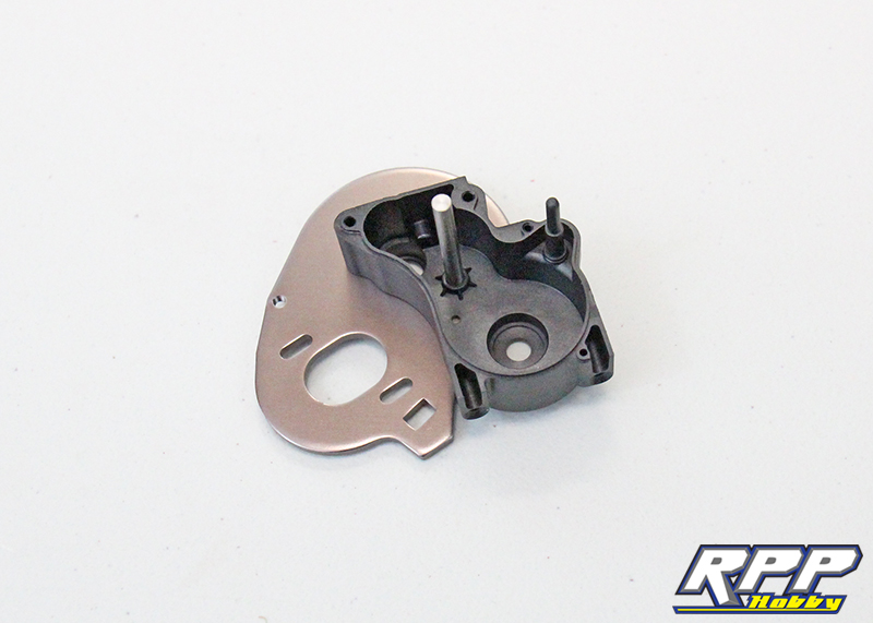
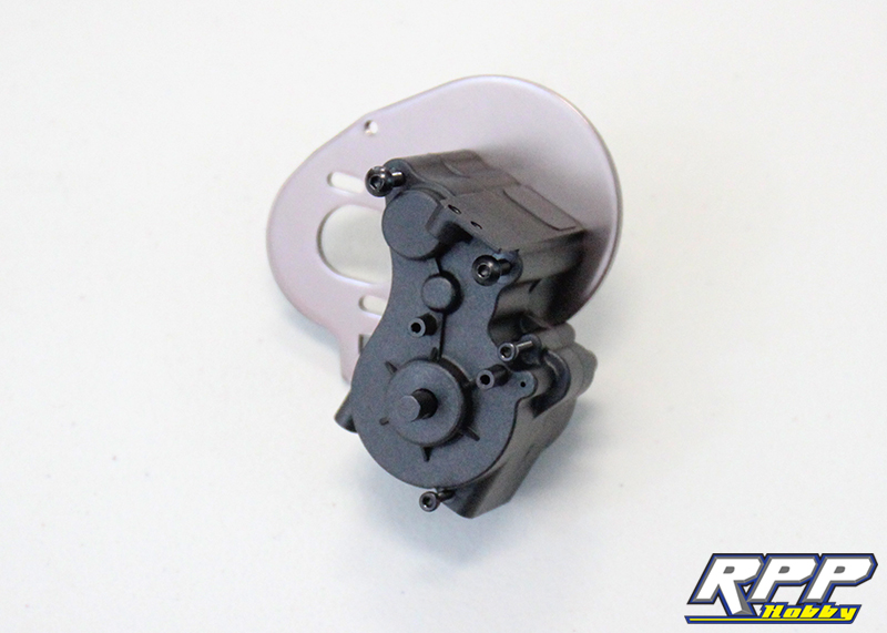
First thing you will need to do is attach the motor plate to the corresponding transmission case housing with the supplied hardware.
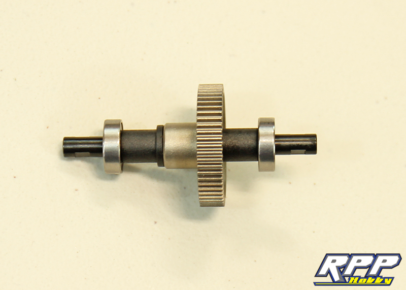
Next it is time to build the main drive gear and output shaft assembly.
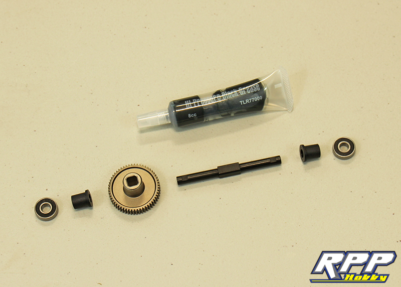
Apply a few dabs of grease to the four flats on the shaft before installing the main gear.
Assemble the two spacers and bearings next. Note the direction of the spacers too, flanged ends sit against the drive gear.
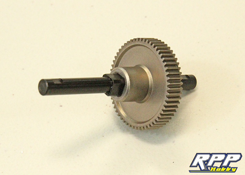
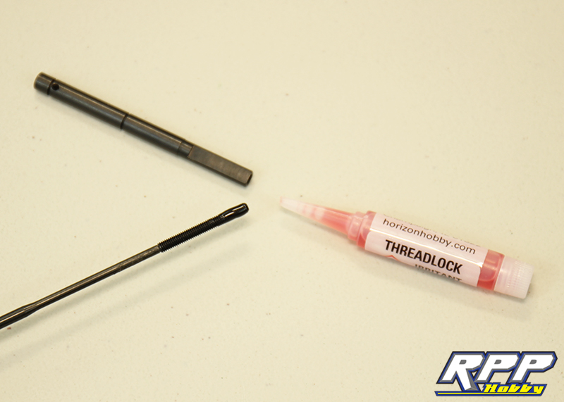
Step A-3 in the manual. Apply thread lock to the long set screw and thread it into the spur gear shaft until it stops and firmly tighten.
Snap the E-clip into place on the opposite end of the spur gear shaft.
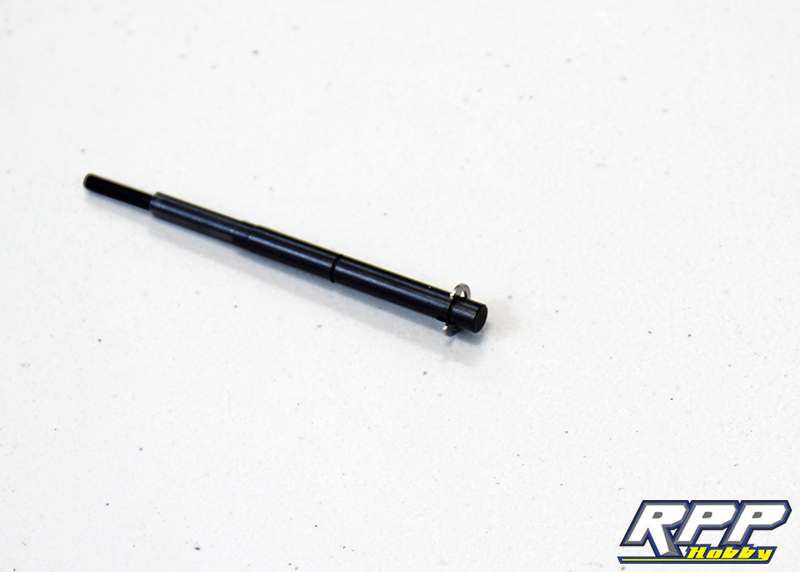
Slide the drive pin for the top gear into place.

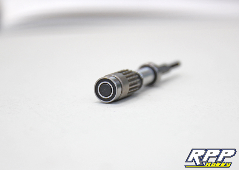
Slide the top gear into place, then the plastic spacer, next E-clip, aluminum spacer and then the first bearing.

Install the thin metal washer up against the first E-clip installed, and slide the second bearing into place.
Locate the trans case and motor plate assembly and install the two pins per page 14, step A-5.
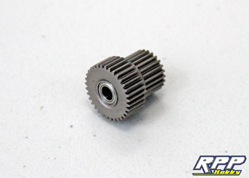
Install the bearings into the idler gear.
Slide the main output shaft into place and the first plastic spacer for the idler gear.
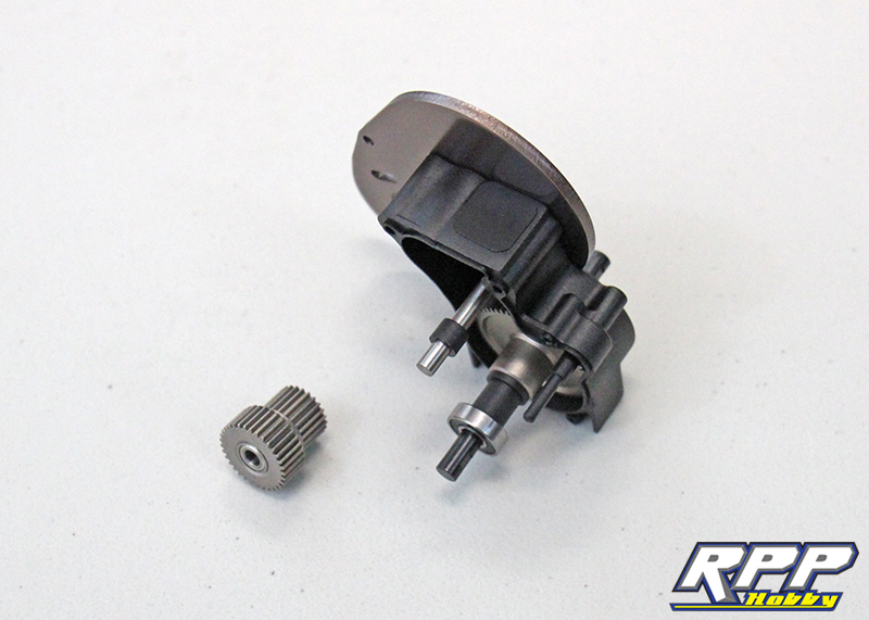
Install the idler gear and second plastic spacer, then slide the spur gear shaft into place.

The manual doesn’t say to grease the transmission gears, but it is probably best if you do. We added a thin layer to all the drive gears.
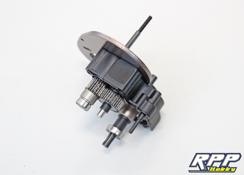
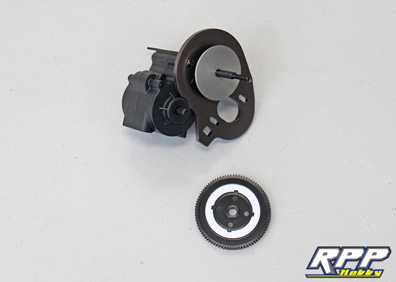
Next locate the second half of the transmission housing and attach it to the transmission assembly with the supplied hardware.
Locate the slipper clutch, slipper pads, spur gear and associated hardware. Install the first slipper plate onto the spur gear shaft and set one slipper pad into place on the spur gear. Note the four tabs that the pads key into.
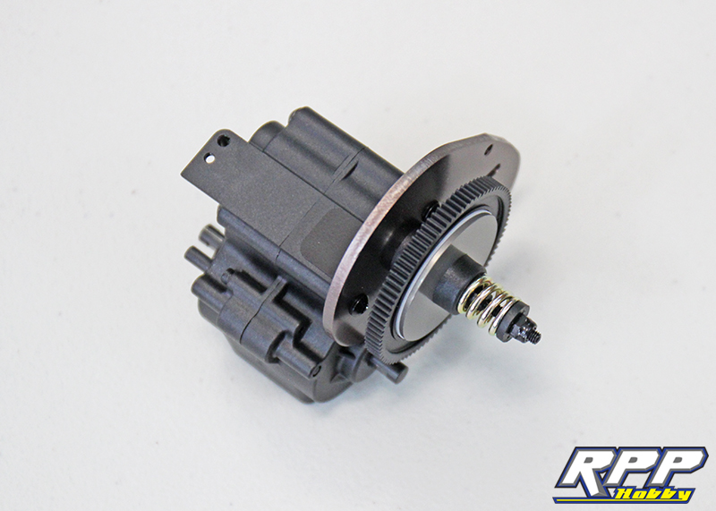
Carefully slide the spur gear into place with the first pad facing the first slipper plate. Make sure the pad stays seated. Slide the second plate and pad into place. We had to hold the transmission vertical to keep everything in place during this step. Then install the slipper spring assembly per the instructions. We tightened our slipper down about half way to start.
Set the motor into place, pull it away from the spur gear and install the motor mount screws finger tight.
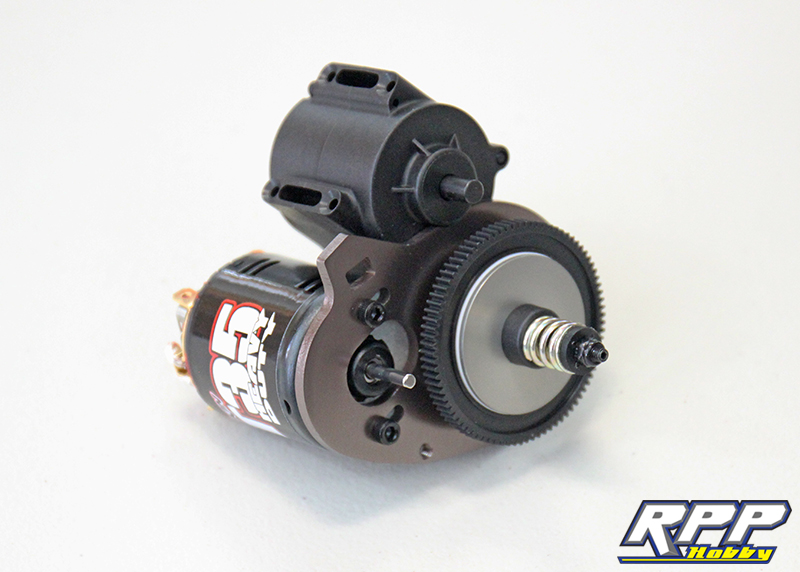
Add a dab of thread lock to the pinion’s set screw.
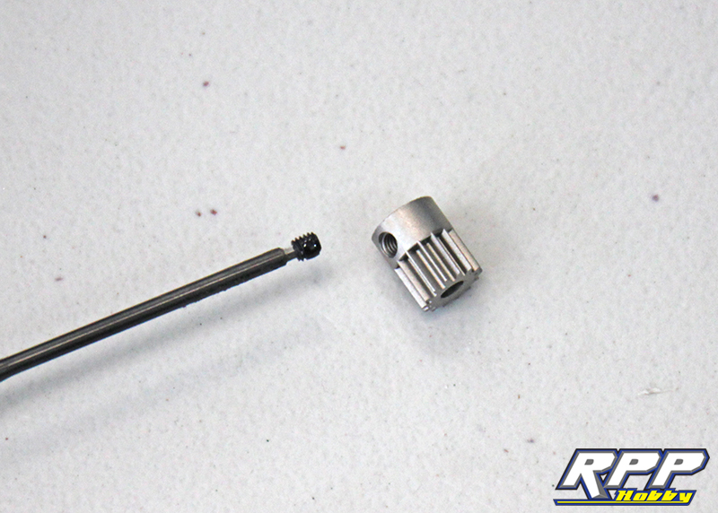
Install the pinion and tighten it down so it lines up with the teeth on the spur gear. Then slid the motor into place with proper gear mesh. There should only be a slight bit of play between the two gears once the motor mount screws are tight. Use a piece of paper to set the mesh, as illustrated on page 18 of the manual, if you are not sure how much play is needed.

Install the small O-ring on the gear cover screw.
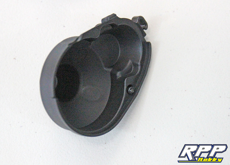
Last step for this installment of our Vaterra Ascender build, fasten the gear cover to the transmission. You now have a complete transmission ready to bolt into the chassis.

That takes care of part 1 of our K5 Ascender build. We are impressed with the quality of the components in the kit now that we have officially dug in! The transmission gears are super quiet when spun by hand, nice and smooth. Tune in for part 2 where we will cover the assembly of the driveshafts and axles, and maybe even utilize a few options parts too. Thanks for reading and stay tuned for more coming soon.
I would be willing to donate a set of my Codyboy weighted axles for a upgrade to this build. I also have a formula to be able to get over 65 degrees of steering.
Ernie